Total Pageviews

Thursday, June 12, 2014

Ephemeriden für die Sonne mit Hilfe des programmierbaren Taschenrechners Casio fx-8000G


Casio fx-8000G
Ein Programm Listing für den CASIO fx-8000G (und verwandte Geräte, die den gleichen "tokenized" BASIC Dialekt verwenden, wie beispielsweise der fx-7000G oder der fx-8500G). Mit Hilfe dieses Programms ist man in der Lage, ohne Nautisches Jahrbuch  oder Verwendung von online-Kalkulatoren die Bildpunktkoordinaten (Grt (Greenwich Stundenwinkel), Declination) der Sonne für ein beliebiges Jahr zu berechnen. Sehr praktisch ist die Möglichkeit, die Uhrzeit im Stunden/Minuten/Sekunden Format einzugeben und die erhaltenen Werte durch Auslesung der Speicherregister "P" und "Q" und Drücken der Tasten

                                     
direkt in das Grad/Minuten/Sekunden Format umzuwandeln. Vielleicht fragst Du dich jetzt "Warum das ganze mit über zwanzig Jahre alter Hardware?"
Es gibt aber ein paar gute Gründe dafür:
- Der fx-8000G verfügt zwar nicht über die zahlreichen features moderner Hochleistungstaschenrechner, er tut aber das, was er tun soll, zuverlässig und schnell. Ich habe meinen ersten fx-8000G 1988 gekauft, der mich durch mein ganzes Studium begleitet und bis 2012 gehalten hat (Tod durch Schaden nach derbem Sturz)
- Gerade dieser scheinbare Mangel an "modernen" stromfressenden Ausstattungsmerkmalen aber ist bei der langfristigen Nutzung von Vorteil. Bestückt mit drei Lithium Knopfzellen 3 Volt, Typ CR2032C, läuft der Rechner bei moderater Nutzung (1/2 h/Tag) mehrere Jahre.
- In der eBucht oder vergleichbaren Portalen ist der fx-8000G oder vergleichbare Rechner für teils einstellige Beträge zu bekommen (zum Vergleich; 1988 betrug der Neupreis etwa 200 DM).
- Der Rechner ist robust aufgebaut, wenn auch nicht wasserdicht. Sicherlich robuster als  das durchschnittliche Notebook oder Laptop. Einen Tip bezüglich der Wasserdichtigkeit habe ich mal irgendwo aufgeschnappt. Einfach den Rechner mit einem gängigen Tiefkühleinschweißgerät in eine durchsichtige Plastiktüte einschweißen.

Das Listing:

Deg
"JAHR":?->Y
"MONAT":?->M
"TAG":?->D
"UTC HMS":?->U:U->V
367xY-Int (7x((Y+Int ((M+9)/12)))/4) Int (275xM-9)+D-678987->J
J+U/24->J:J-51544.5->T:T/36525->K
280.46+0.985647xT->L
L-360x(Int (L-360))->L
357.528+0.9856003xT->N
N-360x(Int (N/360))->N
L+1.915xsin N+0.02xsin (2xN)->A
23.439-0.0000004xT->E
sin-1(sin Exsin A)->Q
2xtan-1(cos Exsin A/(cos Q+cos A))->O
100.07554+0.985647348x(J-U/24-33282)+15.04107xU->G
G-360xInt (G/360)->G
G-O->P
P<0=>P+360->P:Goto 1
P>360=>P-360->P
Lbl 1
P->H
60x(Abs H-Int Abs H)->H
(0.1xInt ((Abs H+0.05)x10))xH->H
Cls
D◿
M◿
Y◿
U◿
P>360=>P-360->P
"SONNE":"GRT":P◿
Q->H
60x(Abs H-Int Abs H)->H
(0.1xInt ((Abs H+0.05))x10)xH->H
Abs Q<1=>HxQ->H
"DEC":Q◿


Anmerkung: Das "Deg" ganz am Anfang dient dem Einstellen des Rechners auf den Altgrad Modus (360°). Das ist wichtig, weil der Rechner neben diesem noch über die zwei Winkelmodi Radiant (Bogenmaß) und Neugrad verfügt. Das Argument "Deg" wird durch Drücken der Tasten "Mode" und "4" erzeugt.


Disclaimer: Alles ist gewissenhaft eingetippt worden, ich hafte aber nicht, wenn ein Tippfehler meiner- oder Ihrerseits Ihre 11 Meter Yacht auf eine Untiefe führen sollte. ;)

Tuesday, May 27, 2014

Ein Programm Listing für den CASIO fx-8000G um kalkulierte Höhe und Azimut zu berechnen (Höhenverfahren in der Astronavigation)

Der programmierbare grafische Taschenrechner CASIO fx-8000G zählt auch heute, über 25 Jahre nach seinem ersten Erscheinen noch längst nicht zum alten Eisen. Mit seinem sehr "schlanken", der Programmiersprache BASIC verwandten "Sprachendialekt" können auch heute noch mathematische Routineanwendungen programmiert werden und fehlerfrei und automatisiert ablaufen. Ein sehr praktisches "feature" dieser genialen kleinen Rechenmaschine; anders als andere Taschenrechner, die z.B. bei Bobby Schenk Erwähnung finden, ist dieses Gerät in der Lage, Positionsangaben im Grad/Minuten/Sekunden Format in ein dezimales Format umzuwandeln und am Schluß der Berechnung auch wieder in das °"´ Format rückzuwandeln (siehe Abb.). Zu Beginn werden Länge und Breite des gegißten Schiffsortes, Grt (Greenwich Stundenwinkel) und Declination (Bildpunktbreite) abgefragt. Je nachdem, ob man sich auf einer östlichen oder westlichen Länge befindet, gibt man bei der Abfrage von E(1):W(-1 eine positive (E) oder negative (W) Zahl ein. Nach Abschluß werden Berechnete Höhe (HC), Azimut (AZ) und (nach Eingabe des gemessenen Winkels) Intercept (also der Unterschied zwischen berechneter und gemessener Gestirnshöhe mit Angabe, ob "hin" zum oder "weg" vom Bildpunkt der Sonne) ausgegeben und sind für weitere Berechnungen in Speicherregister H, Y und I abgelegt. Das Programm beschickt übrigens die gemessene Höhe automatisch mit einer Gesamtbeschickung für 2 Meter Augeshöhe und Messung des Sonnenunterrandes. Das Listing (hach, das erinnert doch sehr an die alten C64 Zeiten, in denen wir Programme aus Zeitschriften abtippten :) ):
Casio fx-8000G
CASIO fx-8000G

Lbl 6
Deg
"BREITE":?->B
"LAENGE":?->L
"GRT":?->G
"DECL."?->D
"E(1):W(-1)":?->C
C<0=>Goto 1:C>0=>Goto 2
Lbl 1:G-L->A:Goto 3
Lbl 2:G+L->A:Goto 3
Lbl 3:sin-1(sin Dxsin B+cos Dxcos Bxcos A)->H
cos-1((sin D-sin Bxsin H)+(cos Hxcos B))->Z
sin A<0=>Z->Y:sin A>0=>360-Z->Y
"HC":H◿
"AZ":Y◿
"GEMESSENER WINKEL"?->W
0->M:0->N:0->O
W≥40°=>W+0°13´->M
W≥25°=>W+0°12´->N
W≥20°=>W+0°11´->O
M->R
R<N=>N->R
R<O=>O->R
R-H->I
I≥0=>Goto 4:I≤0=>Goto 5
Lbl 4
"INTERCEPT HIN":I◿
Goto 6
Lbl 5
"INTERCEPT WEG":I◿
Goto 6

Anmerkung: Das "Deg" ganz am Anfang dient dem Einstellen des Rechners auf den Altgrad Modus (360°). Das ist wichtig, weil der Rechner neben diesem noch über die zwei Winkelmodi Radiant (Bogenmaß) und Neugrad verfügt. Das Argument "Deg" wird durch drücken der Tasten "Mode" und "4" erzeugt.

Die Sequenz

M->R
R<N=>N->R
R<O=>O->R
R-H->I


bestimmt, welche der drei Variablen den höchsten Wert besitzt und damit die gültige Gesamtbeschickung für die Gemessene Höhe darstellt.

Disclaimer: Alles ist gewissenhaft eingetippt worden, ich hafte aber nicht, wenn ein Tippfehler meiner- oder Ihrerseits Ihre 11 Meter Yacht auf eine Untiefe führen sollte. ;)

Die dem Programm zugrunde liegende Formeln sind dem Buch "Astronavigation - ohne Formeln - praxisnah" von Bobby Schenk (Verlag Delius Klasing) entnommen. Danke für dieses Buch, Bobby Schenk! Ohne dieses hätte ich mir nie den Zugang zur Astronavigation erarbeiten können.

Saturday, January 7, 2012

Reviving a ten years old Powerbook Titanium (inverter board fixing)

The backlight of my beloved 2002 Powerbook Titanium DVI 667 MHz failed some months ago. So it went into the attic and collected dust - until now. I gave it a shot and opened the machine using a Torx screwdriver. The insulating foil of the inverter board (the unit that converts direct-current used by the mainboard into high voltage alternating current, that is used by the cold cathode fluorescence lamp illuminating the LCD screen) showed clear signs of a blown joint. Also the inner case of the Tibook showed burn marks.


Signs of a blown connection


I deinstalled the inverter board, opened the insulating foil and inspected it. The inductor coil has five input and two output solder joints. One of the output joints was blown. I took a normal soldering iron and a thin wire of copper and re-connected the joint.


inverter board soldered (not nicely looking i admit)


The original insulating foil for the inverter board was busted during the deinstallation. So i took a normal household plastic bag to improvise an insulation for the IB.


The reinstalled inverter board


Close-up: white and pink are the wires connected with the output joints leading to the backlight bulb


After installation i did put everything back in place, closed the cover, tightened the screws and hoped.....


booting the beast


I was lucky. The trusty old Tibook started and the backlight ignited. Success!

Sunday, October 23, 2011

How to refurbish SunTour Accushift derailleurs


Suntour derailleurs are solid constructed components that perform troublefree for a long period of time. But as years go by they suffer from wear that ultimately leads to failure. From my experience it´s often the tension spring of the parallelogram cage that breaks and leaves the derailleur useless. But how can this spring be exchanged; after all the derailleurs of Suntour are, like the ones of Shimano, rivetted and not fully able to be taken apart, like the ones of e. g. Mavic?!


This how-to illustrates the complete disassembly of Suntour derailleurs, the exchange of damaged parts and finally the re-assembly of the whole mechanism to form a functioning derailleur. This article further wants to show how one can substitute a broken tension spring with a self-made spring made from hardware store parts.

At the beginning i´ll try to define some terms i will use in the further text. The orientation is set according to the normal mounting position on the bicycle. Parts oriented to the center line of the bike are are referred as "inboard", parts oriented outside as "outboard". The parts of the derailleur that bear the pivots are called "front parallelogram body" (FPB) and "rear parallelogram body" (RPB). They guide the two parallelogram arms (inboard parallelogram arm (IPA), outboard parallelogram arm (OPA)). The entity of FPB/RPB and IPA/OPA is called the parallelogram cage.
The parts of a Suntour derailleur that can be disassembled are the pulley cage and the spring-loaded hanger bolt assembly. The pulley cage can be detached removing the M4 set screw. The spring-loaded cage is unloaded rotating it clockwise up to the "twelve o´clock" position and pulling it out of the FPB. The hanger bolt assembly can be opened removing a circlip that secures the bolt.


The dissassembly of the rivetted parallelogram cage is shown in the following part.


Fig. 1: To drive out out the pivots a small hole has to be drilled in the upper extension of their axis. Using a small stub steel nail and a hammer the pivots can be driven out .


Fig. 2: The required drilling to drive out the pivot under the hanger bolt housing has to be performed meticulously, because the position direct above the pivot has to be reached exactly. The picture shows the relative location of the drilling entrance. Because of the more precise mode of action i use hand drillers of the caliber 1.5 mm.


Fig. 3: After drilling the pivots are driven out using the steel nail and a hammer. As a support i use a wood board with a small recess below the pivot.


Fig. 4: To remove the parallelogram spring a brass bushing in the IPA has to be driven out. To do this an M5 screw is placed on top of the fixated IPA and gentle (!) hammering is applied. After this the inner (serrated), the outer brass bushing and the parallelogram spring can be separated.


Fig. 5: If there are no original Suntour spare springs available, a replacement spring can be formed using a pull-spring taken from a local hardware store (outer diameter 12.5, inner diameter 9.5, wire gauge 1.5 mm). To keep the cylindrical form of the spring during the forming and bending, it is hoisted onto a fitting wood stick.


Fig. 6: After bending the spring is shortened using a bolt-cutter and the IPA is reassembled. The self-prepared spring bears the option to control the preloaded tension in a distinct range. Therefore one can fine-tune the shifter and will be able to build it up using a less amount of operating force. The picture shows from front to rear: the broken original Suntour spring, the newly built spare spring (not shortened) and the outer and inner brass bushing.


Fig. 7: A completely disassembled parallelogram cage. Its OPA has been broken. After exchange of the OPA the derailleur could be newly built up.


Fig. 8,9: After thorough cleaning and lubrication the derailleur can be re-assembled. The IPA has to be inserted into the FPB folded to the inner side and is rivetted. The RPB is connected with the IPA and rivetted. As the last step the OPA is mounted and rivetted, which tensions the parallelogram spring.


Fig. 10: The newly rivetted derailleur.


The drill holes can be left untouched or tinned which masks the the modification of the derailleur. To leave the drill holes as they are bears the benefit that the derailleur can be opened for maintenance very easy. Another application for the dissassembly of the rivetted parallelogram cage is the completion of a derailleur from parts of broken derailleurs. This is a valid option since the last "generation" of Suntour derailleurs are identical in construction (leave out the Superbe Pro derailleur).

How to touch up vintage SunTour index control thumbshifters


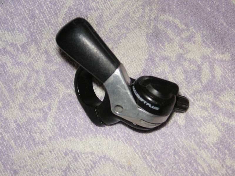
Many of you may know them, many still drive them on their vintage mountain bike or randonneur and appreciate them because of their low weight and ability to be run in friction mode when the lever or the derailleur are somehow damaged. But as time goes by and weather and dust keep on having a bad influence on the delicate mechanics inside such a lever one may feel the need to overhaul the lever to re-insure correct indexing. This how-to article mainly relies on the pictures that illustrate the complete "clean-lube-adjust" procedure done with a 1990 7-speed Suntour XC ltd. thumb shifter. But this can be applied to all modern Accushift plus indexed shift levers Suntour produced during it´s last few years before it went out of business, even the road bike down tube shifters that are mounted on braze-on studs do bear the same interchangeable mechanics inside and therefore can serve as a spare part supply.


Fig. 1: The thumb shifter (rear derailleur, 7-speed) connected to the mounting bracket.


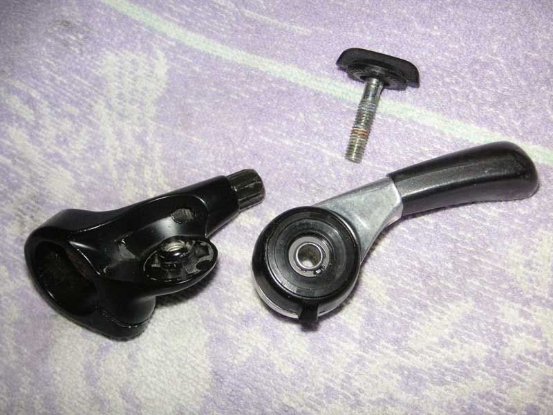
Fig. 2: The toggle screw removed which also serves the clamping of the friction/index mechanism in order to adjust the friction of the system.


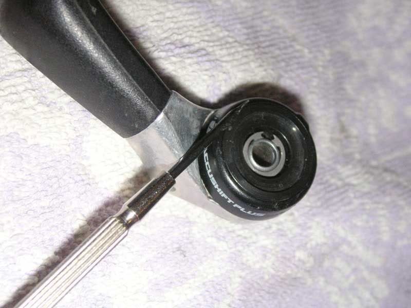
Fig. 3: The mechanism inside the lever can be opened by removing a circlip in the recession of the cap assembly using a flat head screwdriver.


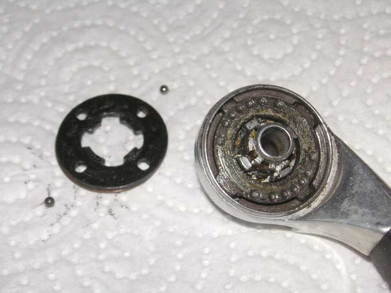
Fig. 4: The cap assembly opened. The upper part of the friction/index mechanism is visible.


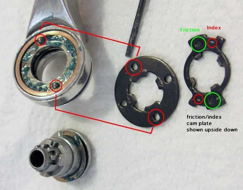
Fig. 5: The ball holder plate with the two indexing steel balls. The balls are inserted into the holes in line with the broad inner noses (not the ones marked with an engraved "ball" symbol!).


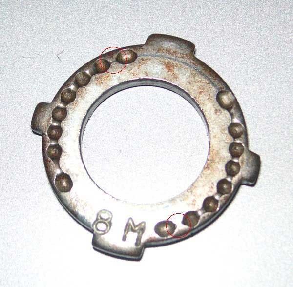
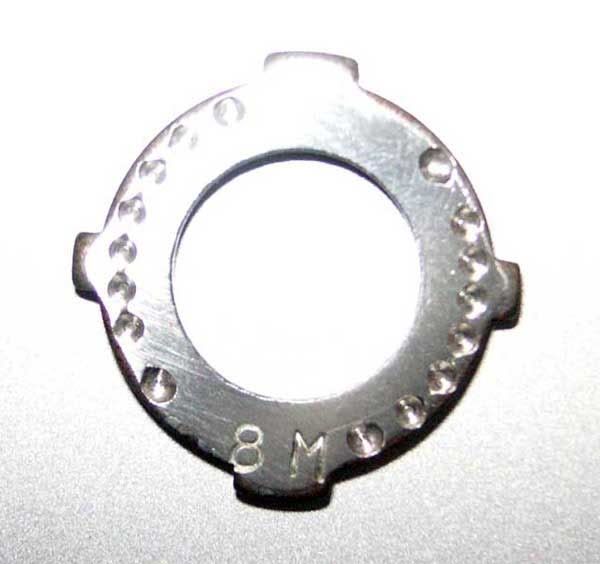
Fig. 6: The indexing cam ring. Seven pits on each side serve as resting points for the two indexing balls. This cam ring still looks good and needs only cleaning.


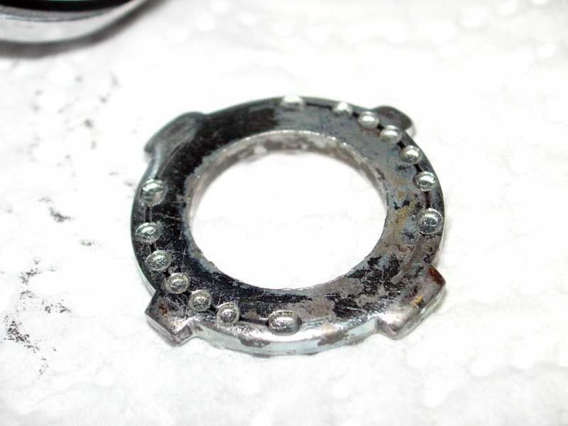
Fig. 6: This cam ring taken from another thumb shifter (Suntour XC Pro) suffers from massive wear. The shifter was unable to "hold gears" and general shifting performance was poor. Note the grooves between the index pits which prevented the correct positioning of the lever.


Fig. 7: The index cam plate can be refurbished by grinding the surface until the grooves have disappeared. The index pits have to be deepened using a dremel tool and a fine abrasive tip.


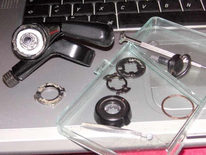
Fig. 8: The loss of thickness of the index cam plate has to be compensated by an additional washer. I prepared one by cutting and sanding an old credit card type plastic card (white ring inside the lever). During reassembly the new washer is placed under the index cam plate.


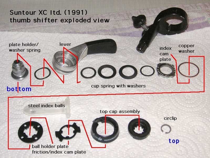
Fig. 9: An exploded view of all parts of the thumb shifter


Fig. 10: After thorough cleaning of all parts the parts are greased with a ball bearing grease and the lever is reassembled according to fig. 7. The ball holder plate must be inserted like it is shown in the picture. The friction/index cam plate has two areas, one with a pit which engages the friction mode and one with a flat surface which presses the indexing balls against the index cam plate and ensures the latching of the gears. For reassembly i found it suitable to insert the friction/index cam plate in friction position because the pits help to hold the whole mechanism in correct place. After placing of the cap assembly the whole lever can be secured by inserting the circlip. Although there is some special tool for handling circlips, with a little bit of patience and practice this step can be done using two flat head screwdrivers.


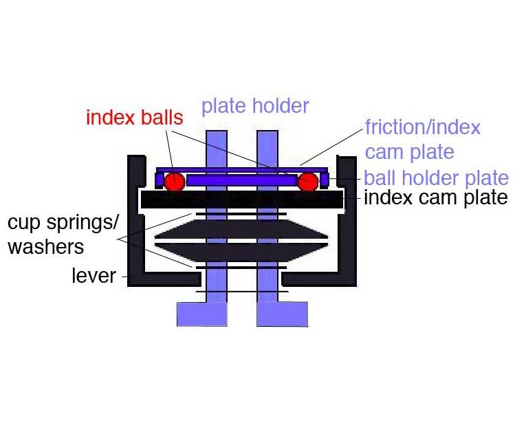
Fig. 11: A scheme of all moving parts (black), the fixed part of the mechanics (blue) and the index balls (red), also visible is the correct arangement of the cup springs and washers.