
Many of you may know them, many still drive them on their vintage mountain bike or randonneur and appreciate them because of their low weight and ability to be run in friction mode when the lever or the derailleur are somehow damaged. But as time goes by and weather and dust keep on having a bad influence on the delicate mechanics inside such a lever one may feel the need to overhaul the lever to re-insure correct indexing. This how-to article mainly relies on the pictures that illustrate the complete "clean-lube-adjust" procedure done with a 1990 7-speed Suntour XC ltd. thumb shifter. But this can be applied to all modern Accushift plus indexed shift levers Suntour produced during it´s last few years before it went out of business, even the road bike down tube shifters that are mounted on braze-on studs do bear the same interchangeable mechanics inside and therefore can serve as a spare part supply.
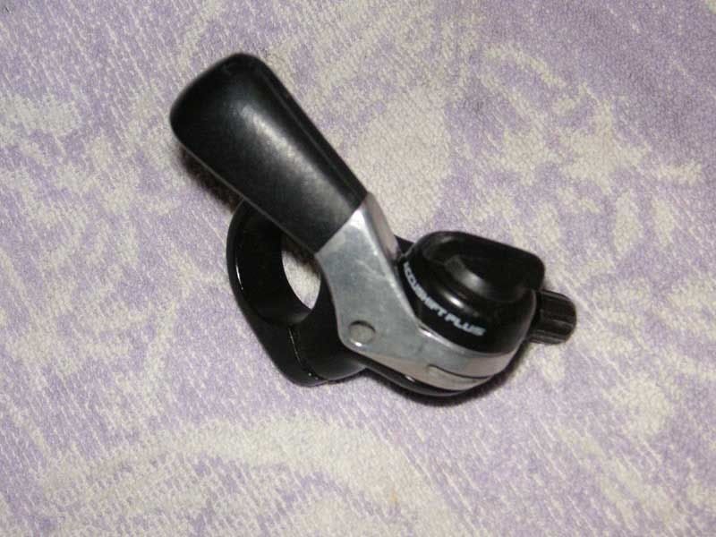
Fig. 1: The thumb shifter (rear derailleur, 7-speed) connected to the mounting bracket.
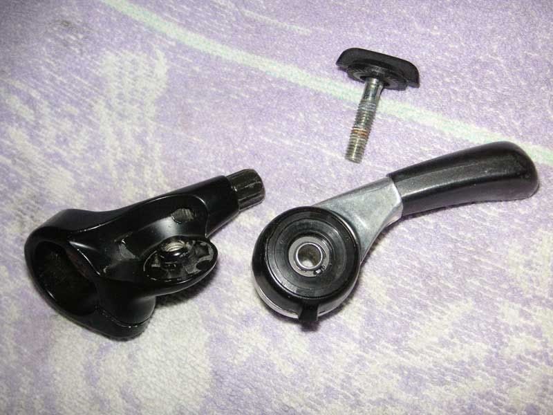
Fig. 2: The toggle screw removed which also serves the clamping of the friction/index mechanism in order to adjust the friction of the system.
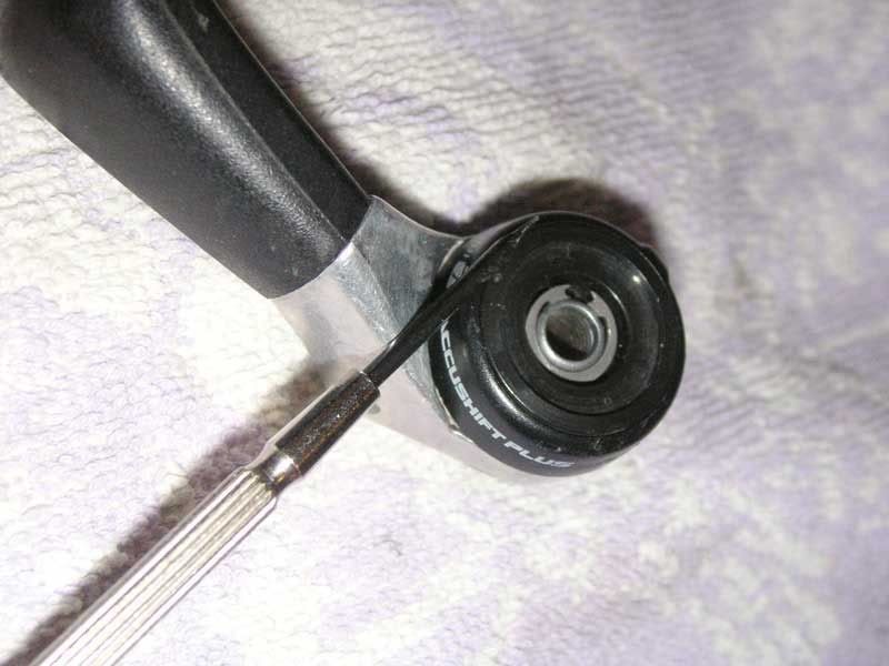
Fig. 3: The mechanism inside the lever can be opened by removing a circlip in the recession of the cap assembly using a flat head screwdriver.

Fig. 4: The cap assembly opened. The upper part of the friction/index mechanism is visible.
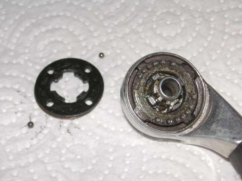
Fig. 5: The ball holder plate with the two indexing steel balls. The balls are inserted into the holes in line with the broad inner noses (not the ones marked with an engraved "ball" symbol!).
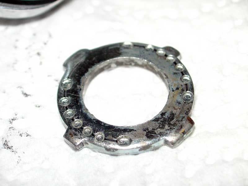
Fig. 6: The indexing cam ring. Seven pits on each side serve as resting points for the two indexing balls. This cam ring still looks good and needs only cleaning.
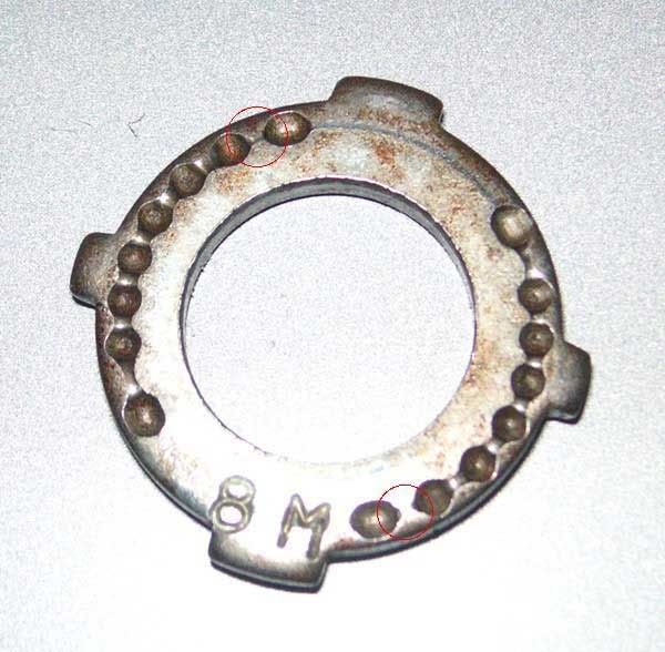
Fig. 6: This cam ring taken from another thumb shifter (Suntour XC Pro) suffers from massive wear. The shifter was unable to "hold gears" and general shifting performance was poor. Note the grooves between the index pits which prevented the correct positioning of the lever.
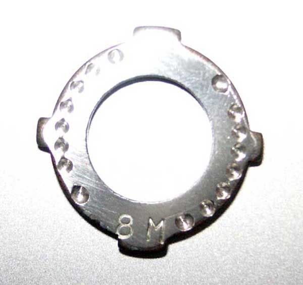
Fig. 7: The index cam plate can be refurbished by grinding the surface until the grooves have disappeared. The index pits have to be deepened using a dremel tool and a fine abrasive tip.
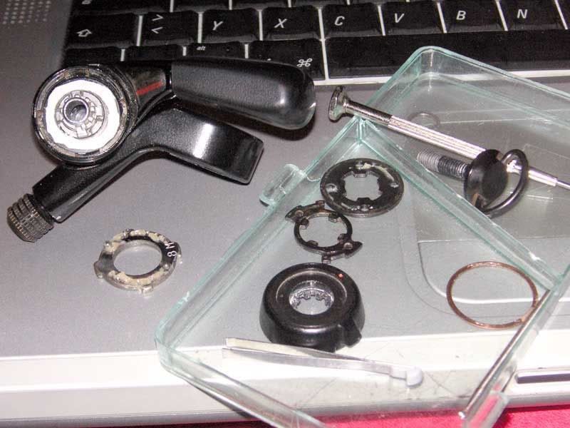
Fig. 8: The loss of thickness of the index cam plate has to be compensated by an additional washer. I prepared one by cutting and sanding an old credit card type plastic card (white ring inside the lever). During reassembly the new washer is placed under the index cam plate.
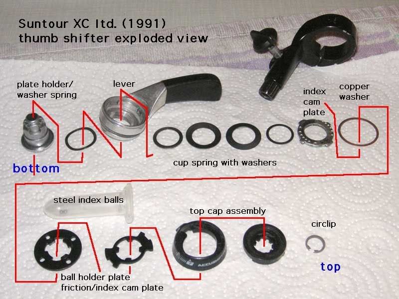
Fig. 9: An exploded view of all parts of the thumb shifter
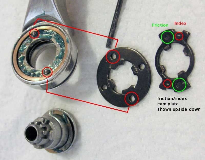
Fig. 10: After thorough cleaning of all parts the parts are greased with a ball bearing grease and the lever is reassembled according to fig. 7. The ball holder plate must be inserted like it is shown in the picture. The friction/index cam plate has two areas, one with a pit which engages the friction mode and one with a flat surface which presses the indexing balls against the index cam plate and ensures the latching of the gears. For reassembly i found it suitable to insert the friction/index cam plate in friction position because the pits help to hold the whole mechanism in correct place. After placing of the cap assembly the whole lever can be secured by inserting the circlip. Although there is some special tool for handling circlips, with a little bit of patience and practice this step can be done using two flat head screwdrivers.
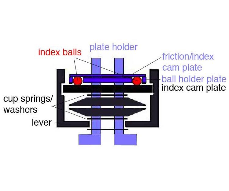
Fig. 11: A scheme of all moving parts (black), the fixed part of the mechanics (blue) and the index balls (red), also visible is the correct arangement of the cup springs and washers.